Physically Based Lens Flare
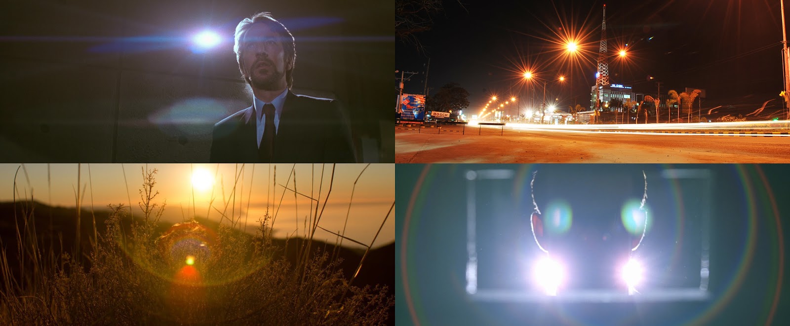
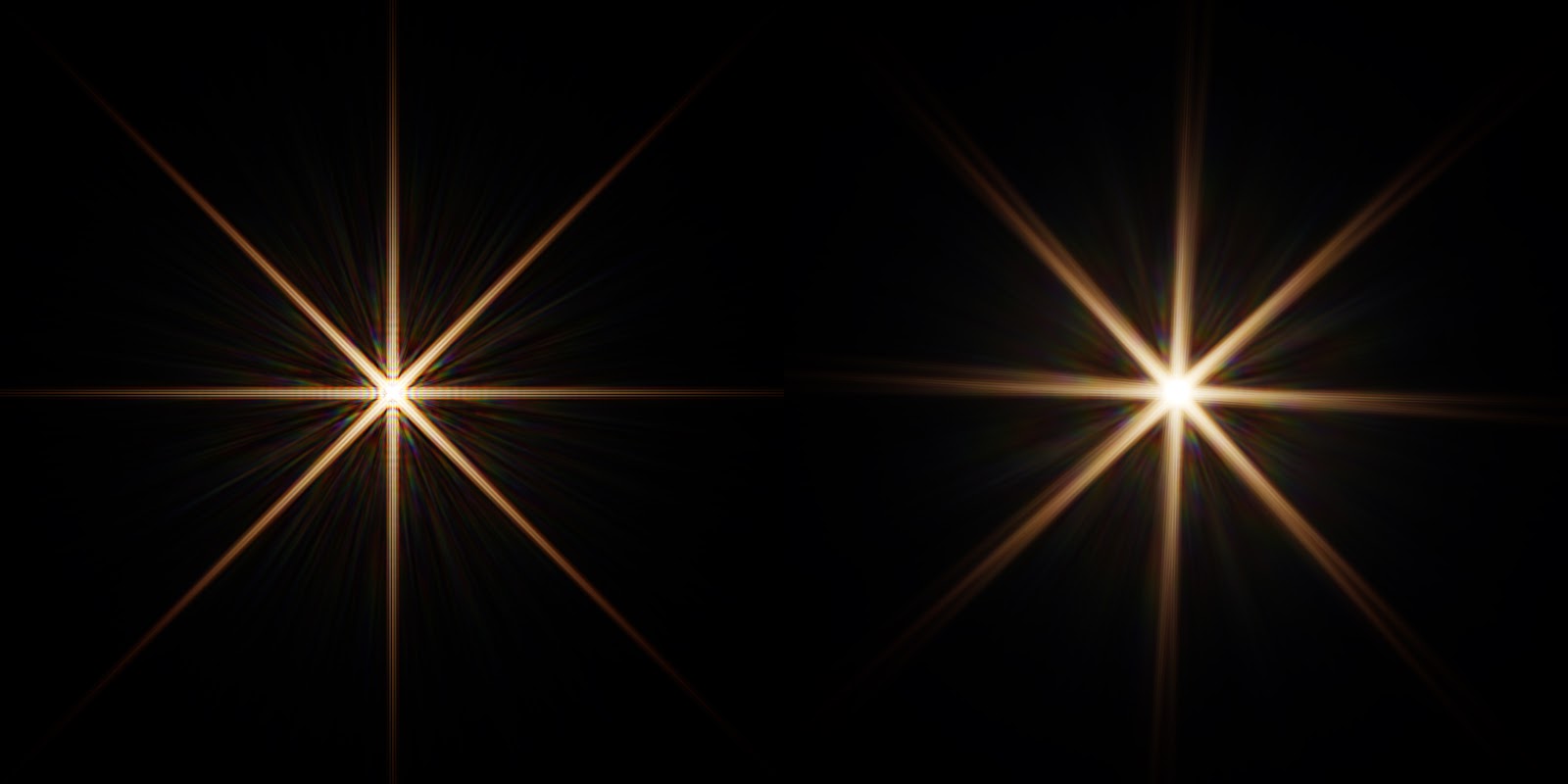
While playing Horizon Zreo Dawn I got inspired by the lens flare they supported and decided to look into implementing some basic ones in Stingray. There were four types of flare I was particularly interested in:
Code and Results
Once finished I'll do a follow up blog post on the Camera Lens Flare plugin, but for now I want to share the implementation details of the high-quality ghosts which are an implementation of "Physically-Based Real-Time Lens Flare Rendering". All the code used to generate the images and videos of this article can can be found on github.com/greje656/PhysicallyBasedLensFlare.
Ghosts
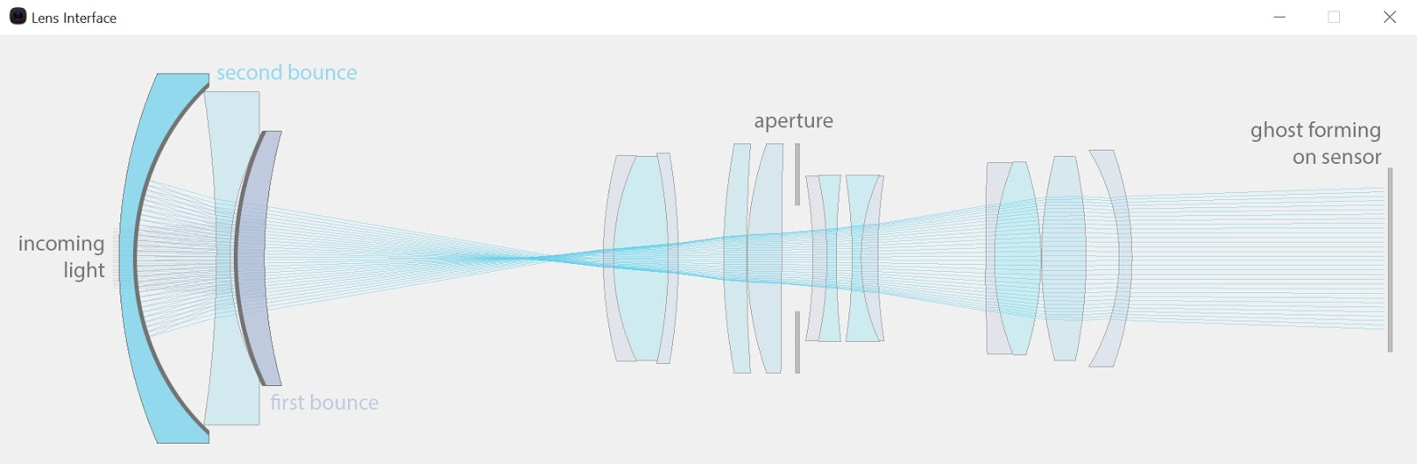
The basic idea of the "Physically-Based Lens Flare" paper is to ray trace "bundles" into a lens system which will end up on a sensor to form a ghost. A ghost here refers to the de-focused light that reaches the sensor of a camera due to the light reflecting off the lenses. Since a camera lens is not typically made of a single optical lens but many lenses there can be many ghosts that form on it's sensor. If we only consider the ghosts that are formed from two bounces, that's a total of nCr(n,2) possible ghosts combinations (where n is the number of lens components in a camera lens)
Lens Interface Description
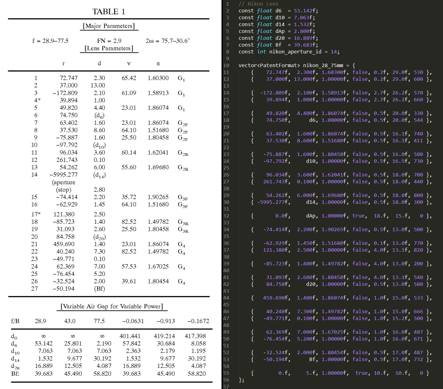
Ok let's get into it. To trace rays in an optical system we obviously need to build an optical system first. This part can be tedious. Not only have you got to find the "Lens Prescription" you are looking for, you also need to manually parse it. For example parsing the Nikon 28-75mm patent data might look something like this:
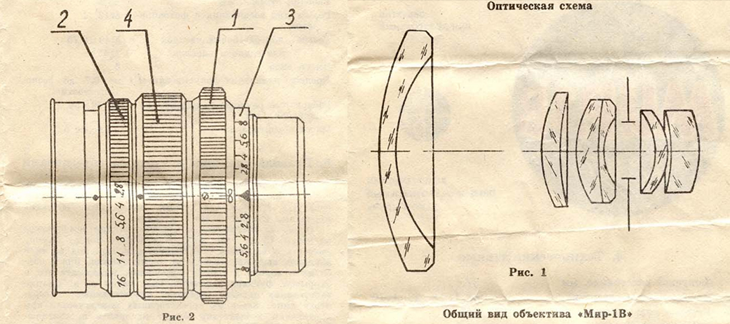
There is no standard way of describing such systems. You may find all the information you need from a lens patent, but often (especially for older lenses) you end up staring at an old document that seems to be missing important information required for the algorithm. For example, the Russian lens MIR-1 apparently produces beautiful lens flare, but the only lens description I could find for it was this:
There is no standard way of describing such systems. You may find all the information you need from a lens patent, but often (especially for older lenses) you end up staring at an old document that seems to be missing important information required for the algorithm. For example, the Russian lens MIR-1 apparently produces beautiful lens flare, but the only lens description I could find for it was this:
Ray Tracing
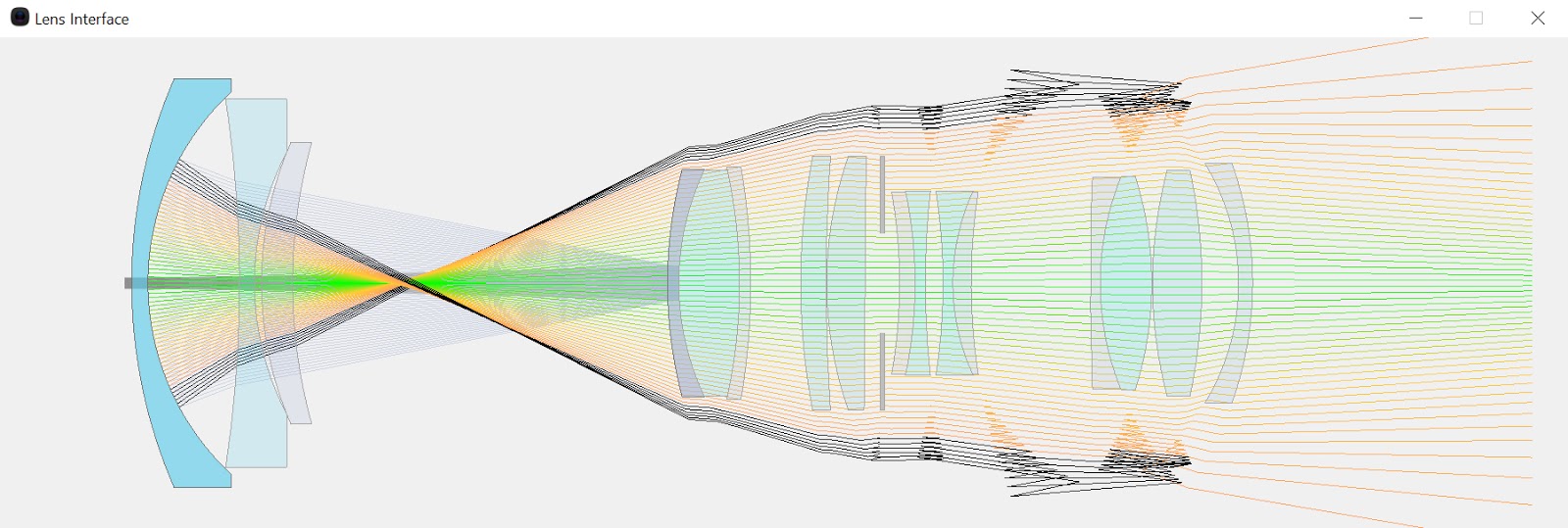
Once you have parsed your lens description into something your trace algorithm can consume, you can then start to ray trace. The idea is to initialize a tessellated patch at the camera's light entry point and trace through each of the points in the direction of the incoming light. There are a couple of subtleties to note regarding the tracing algorithm.
First, when a ray misses a lens component the raytracing routine isn't necessarily stopped. Instead if the ray can continue with a path that is meaningful the ray trace continues until it reaches the sensor. Only if the ray misses the sphere formed by the radius of the lens do we break the raytracing routine. The idea behind this is to get as many traced points to reach the sensor so that the interpolated data can remain as continuous as possible. Rays track the maximum relative distance it had with a lens component while tracing through the interface. This relative distance will be used in the pixel shader later to determine if a ray had left the interface.
Secondly, a ray bundle carries a fixed amount of energy so it is important to consider the distortion of the bundle area that occurs while tracing them. In In the paper, the author states:
"At each vertex, we store the average value of its surrounding neighbours. The regular grid of rays, combined with the transform feedback (or the stream-out) mechanism of modern graphics hardware, makes this lookup of neighbouring quad values very easy"
This works fairly well but is expensive. Something that I intend to improve in the future.
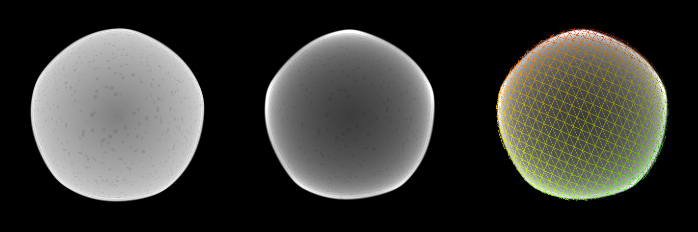
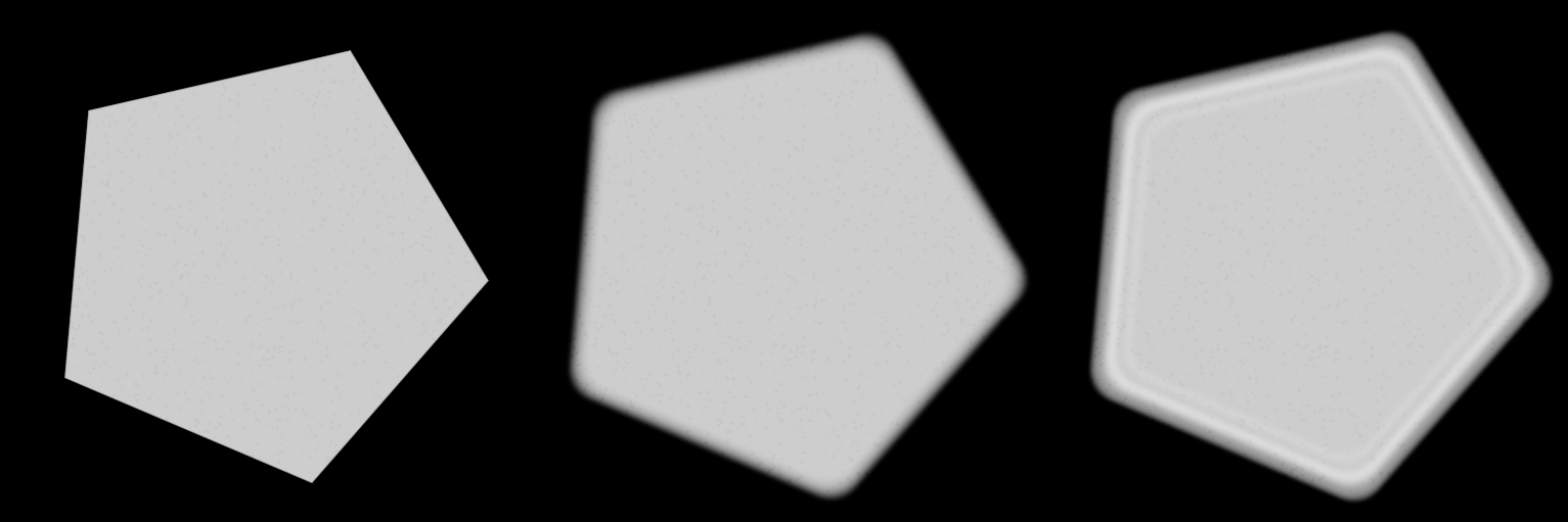
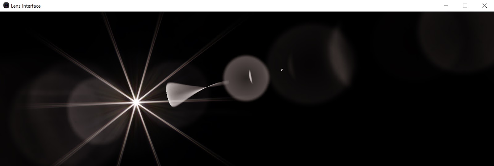
Now that we have a traced patch we need to make some sense out of it. The patch "as is" can look intimidating at first. Due to early exits of some rays the final vertices can sometimes look like something went terribly wrong. Here is a particularly distorted ghost:
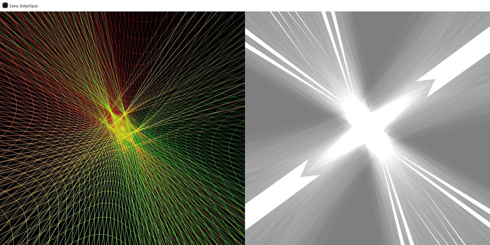
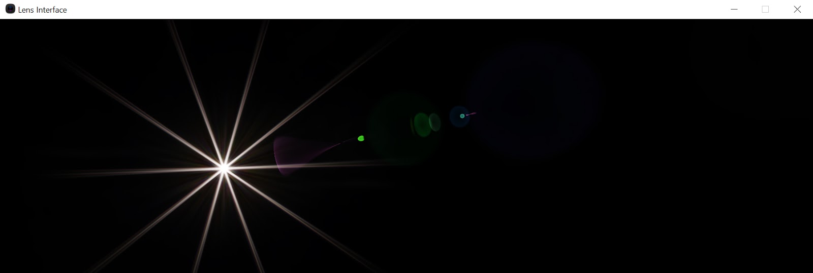
The first thing to do is discard pixels that exited the lens system:
if(max_relative_distance < 1.0f) discard;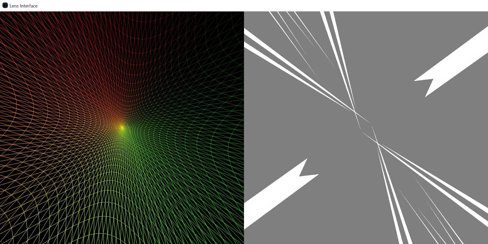
Then we can discard the rays that didn't have any energy as they entered to begin with (say outside the sun disk):
float lens_distance = length(entry_coordinates.xy);
float sun_disk = 1 - saturate((lens_distance - 1.f + fade)/fade);
sun_disk = smoothstep(0, 1, sun_disk);
//...
float intensity2 = sun_disk;
float intensity = intensity1 * intensity2;
if(intensity == 0.f) discard;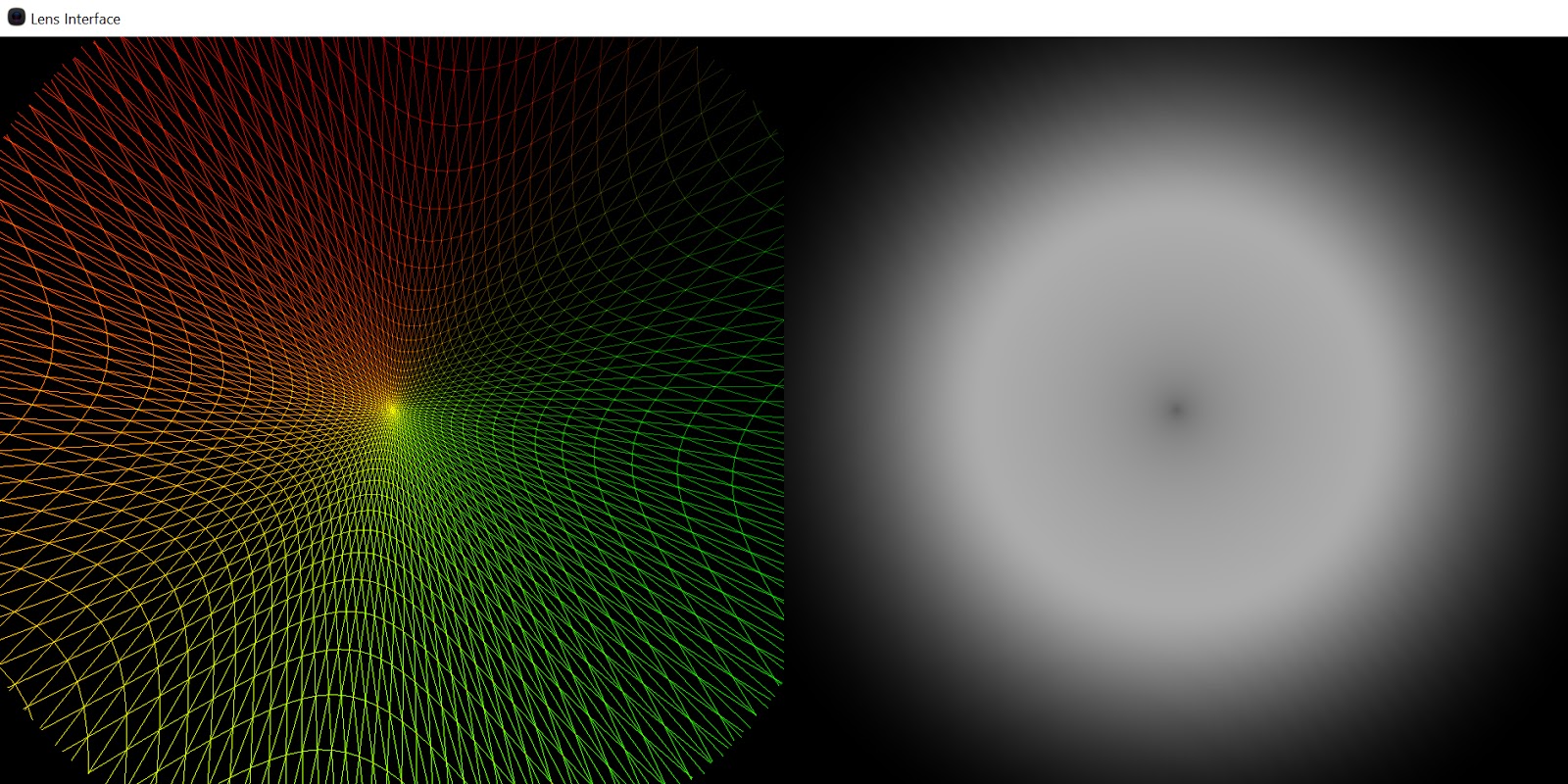
Then we can discard the rays that we're blocked by the aperture:
//...
float intensity3 = aperture_sample;
float intensity = intensity1 * intensity2 * intensity3;
if(intensity == 0.f) discard;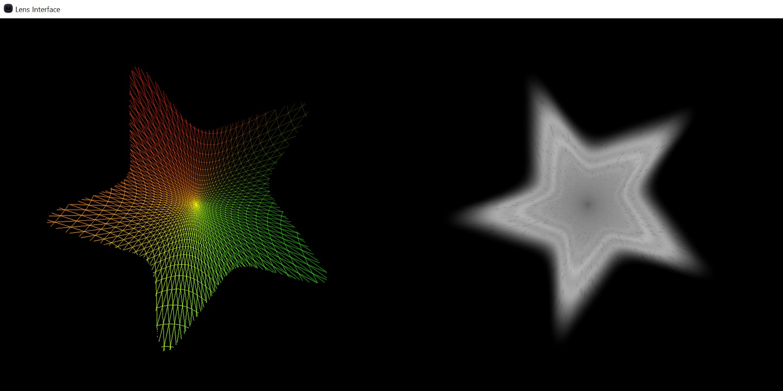
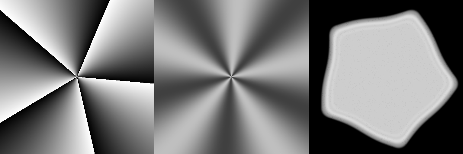
Finally we adjust the radiance of the beams based on their final areas:
//...
float intensity4 = (original_area/(new_area + eps)) * energy;
float intensity = intensity1 * intensity2 * intensity3 * intensity4;
if(intensity == 0.f) discard;
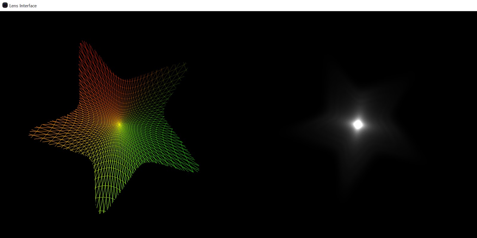
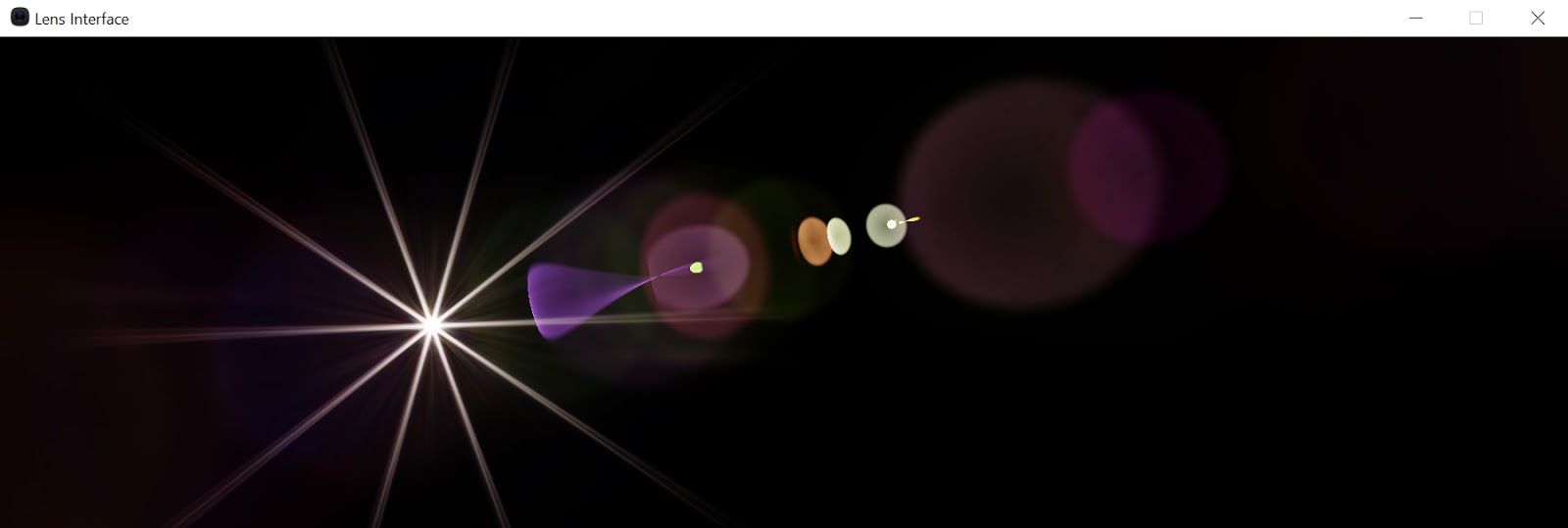
The final value is the rgb reflectance value of the ghost modulated by the incoming light color:
float3 color = intensity * reflectance.xyz * TempToColor(INCOMING_LIGHT_TEMP);Aperture
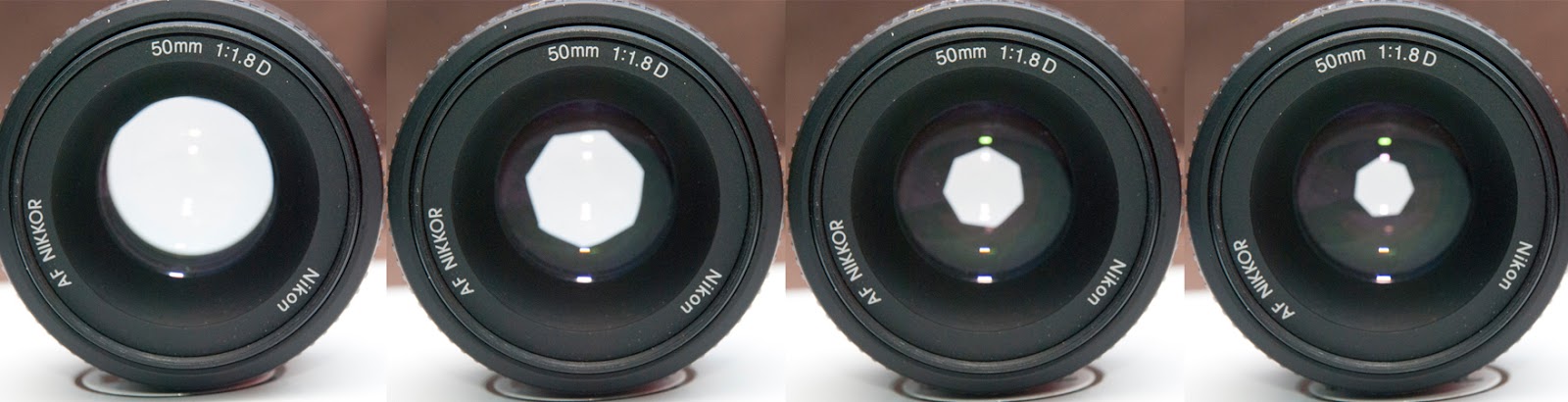
The aperture shape is built procedurally. As suggested by Padraic Hennessy's blog I use a signed distance field confined by "n" segments and threshold it against some distance value. I also experimented with approximating the light diffraction that occurs at the edge of the apperture blades using a simple function:
Finally, I offset the signed distance field with a repeating sin function which can give curved aperture blades:
Starburst
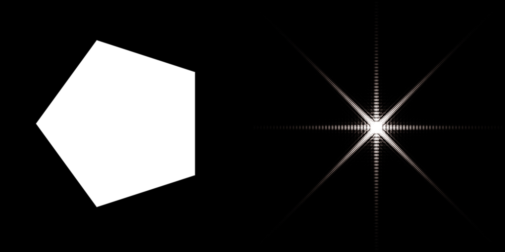
The starburst phenomena is due to light diffraction that passes through the small aperture hole. It's a phenomena known as the "single slit diffraction of light". The author got really convincing results to simulate this using the Fraunhofer approximation. The challenge with this approach is that it requires bringing the aperture texture into Fourier space which is not trivial. In previous projects I used Cuda's math library to perform the FFT of a signal but since the goal is to bring this into Stingray I didn't want to have such a dependency. Luckily I found this little gem posted by Joseph S. from intel. He provides a clean and elegant compute implementation of the butterfly passes method which bring a signal to and from Fourier space. Using it I can feed in the aperture shape and extract the Fourier Power Spectrum:
This spectrum needs to be filtered further in order to look like a starburst. This is where the Fraunhofer approximation comes in. The idea is to basically reconstruct the diffraction of white light by summing up the diffraction of multiple wavelengths. The key observation is that the same Fourier signal can be used for all wavelengths. The only thing needed is to scale the sampling coordinates of the Fourier power spectrum:
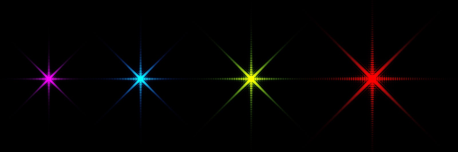
Summing up the wavelengths gives the starburst image. To get more interesting results I apply an extra filtering step. I use a spiral pattern mixed with a small rotation to get rid of any left over radial ringing artifacts (judging by the author's starburst results I suspect this is a step they are also doing):
Anti Reflection Coating
While some appreciate the artistic aspect of lens flare, lens manufacturers work hard to minimize them by coating lenses with anti-reflection coatings. The coating applied to each lenses are usually designed to minimize the reflection of a specific wavelength. They are defined by their thickness and index of refraction. Given the wavelength to minimize reflections for, and the IORs of the two medium involved in the reflection (say n0 and n2), the ideal IOR (n1) and thickness (d) of the coating are defined as n1 = sqrt(n0·n2) and d=λ/4·n1. This is known as a quarter wavelength anti-reflection coating. I've found this site very helpful to understand this phenomenon.
In the current implementation each lens coating specifies a wavelength the coating should be optimized for and the ideal thickness and IOR are used by default. I added a controllable offset to thicken the AR coating layer in order to conveniently reduce it's anti-reflection properties:
Optimisations
Currently the full cost of the effect for a Nikon 28-75mm lens is 12ms (3ms to ray march 352x32x32 points and 9ms to draw the 352 patches). The performance degrades as the sun disk is made bigger since it results in more and more overshading during the rasterisation of each ghosts. With a simpler lens interface like the 1955 Angenieux the cost decreases significantly. In the current implementation every possible "two bounce ghost" is traced and drawn. For a lens system like the Nikon 28-75mm which has 27 lens components, that's n!/r!(n-r)! = 352 ghosts. It's easy to see that this number can increase dramatically with the number of component.
An obvious optimization would be to skip ghosts that have intensities so low that their contributions are imperceptible. Using Compute/DrawIndirect it would be fairly simple to first run a coarse pass and use it to cull non contributing ghosts. This would reduce the compute and rasterization pressure on the gpu dramatically. Something I intend to do in future.
Conclusion
I'm not sure if this approach was ever used in a game. It would probably be hard to justify it's heavy cost. I feel this would have a better use case in the context of pre-visualization where a director might be interested in having early feedback on how a certain lens might behave in a shot.
Finally, be aware the author has filled a patent for the algorithm described in his paper, which may put limits on how you may use parts of what is described in my post. Please contact the paper's author for more information on what restrictions might be in place.
Note: Original post made on the: Autodesk Stingray Blog